If you are evaluating sedimentation technologies for a water or wastewater treatment project, chances are you have come across lamella clarifiers — and wondered what makes them so much more space-efficient than conventional settling basins. The answer lies in a deceptively simple engineering principle: by introducing inclined plates into the settling zone, these systems multiply the effective separation area many times over without expanding the physical footprint. In this guide, we break down the lamella clarifier working principle step by step, explain the key components and design parameters that affect real-world performance, and help you determine whether a lamella system is the right fit for your next project.
A lamella clarifier — also known as an inclined plate settler — is a type of high-rate sedimentation device used in water and wastewater treatment to separate suspended solids from liquids. It works by directing incoming water through a series of inclined plates (lamellae), typically set at a 55° to 60° angle, which dramatically increases the effective settling area within a compact footprint.
The underlying principle is rooted in shallow-depth sedimentation theory. According to Stokes' Law, the settling velocity of a particle depends on its size, density, and the viscosity of the surrounding fluid — but the distance it must travel to reach a collection surface is equally important. By introducing closely spaced inclined plates, a lamella clarifier reduces that settling distance to just the gap between adjacent plates (typically 50–100 mm), rather than the full depth of a conventional basin.
Here is how the process works step by step:
1. Influent Distribution. Pretreated water (usually after coagulation and flocculation) enters the clarifier through an inlet distribution zone, which evenly spreads the flow across the full width of the unit. Uniform distribution is critical — it prevents short-circuiting and ensures every plate pack channel receives an equal hydraulic load.
2. Inclined Plate Settling. As water flows upward between the inclined plates, suspended particles settle onto the plate surfaces under the force of gravity. Because the plates are angled, settled solids slide downward along the plate surface toward the sludge collection hopper at the bottom, while the clarified water continues to rise.
3. Clarified Water Collection. At the top of the plate pack, clarified effluent exits through a flow control system — typically a series of precision-drilled orifices or weirs — that draws water evenly across the entire plate area. This ensures that all plates contribute equally to the treatment process and that maximum settling efficiency is achieved.
4. Sludge Removal. The accumulated sludge, having slid down the inclined plates, collects in a hopper at the base of the unit. It is periodically or continuously removed via a sludge discharge system (gravity drain or pump), keeping the clarifier operating at steady-state performance.
This inclined plate design allows a lamella clarifier to achieve an effective settling area up to eight times greater than a conventional flat-bottom basin of the same footprint. The result is significantly higher throughput in a fraction of the space — a key reason why lamella clarifiers are widely used in municipal water supply, industrial wastewater treatment, and process water applications where land and budget constraints are factors.
Understanding the key components of a lamella clarifier helps engineers and operators evaluate equipment quality, troubleshoot performance issues, and make informed purchasing decisions. While designs vary by manufacturer, most lamella clarifiers share the following core components:
The inlet zone is responsible for receiving pretreated water and distributing it evenly across the width of the clarifier. It typically includes baffles, perforated walls, or energy-dissipating chambers that reduce turbulence and prevent short-circuiting. Proper inlet design is essential — uneven flow distribution is one of the most common causes of poor clarifier performance.
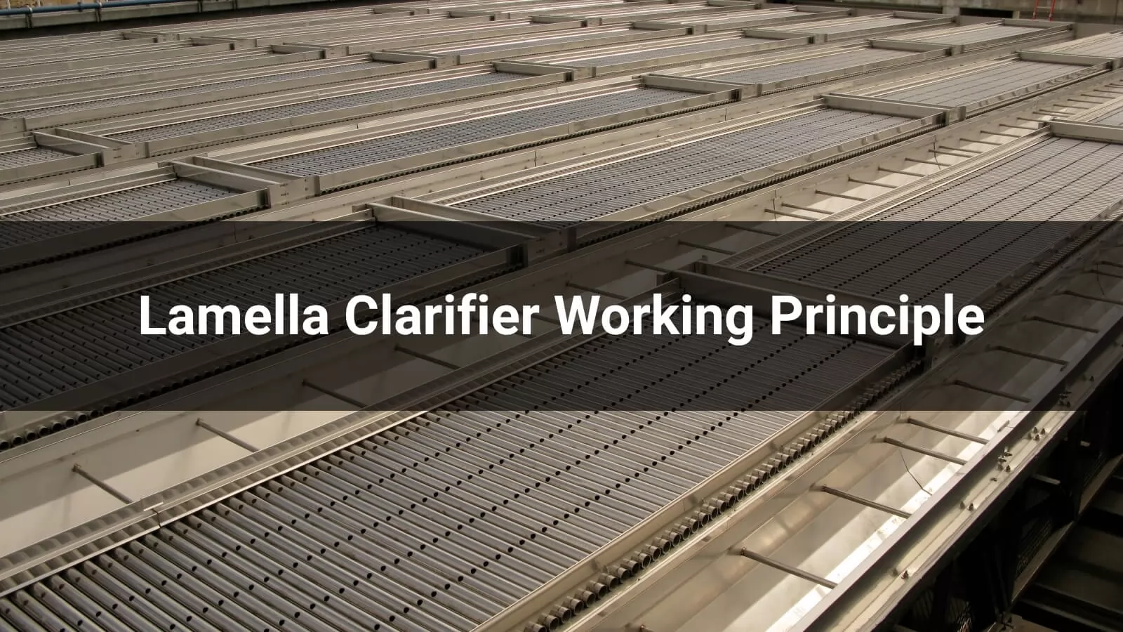
The plate pack is the heart of the system. It consists of a series of parallel plates — usually made from stainless steel, PVC, or polypropylene — installed at an angle of 55° to 60° from the horizontal. The plates are spaced at regular intervals (commonly 50 mm, 80 mm, or 100 mm) depending on the application and solids loading. Plate length typically ranges from 1.5 m to 3.0 m. The inclined surface provides the settling area where suspended particles separate from the water column.
A rigid structural frame holds the plate pack in position and bears the combined weight of the plates and accumulated solids. Frames are commonly fabricated from stainless steel or carbon steel with protective coatings. Structural integrity is critical — any sagging or misalignment in the plate pack will disrupt flow patterns and reduce settling efficiency.
Located above the plate pack, the flow control system ensures that clarified water is drawn evenly from every plate channel. This is typically achieved through a manifold of stainless steel tubes, each fitted with precision-drilled metering orifices. Uniform hydraulic withdrawal across the full plate area is what distinguishes a well-engineered lamella clarifier from a poorly performing one.
Clarified water exiting the flow control system is gathered in a collection trough or launder, which directs it to the downstream treatment process or discharge point. Launders are designed to maintain low-velocity, non-turbulent flow to avoid re-suspending any residual fine particles.
At the base of the clarifier, a hopper collects the settled solids that slide down the inclined plates. The hopper is typically designed with steep walls (60° or greater) to promote gravity-driven sludge consolidation. Sludge is removed either continuously or on a timed cycle via gravity drain valves, sludge pumps, or screw conveyors, depending on the solids volume and consistency.
The outer enclosure can be a purpose-built stainless steel or carbon steel tank, a concrete basin, or even a retrofit within an existing sedimentation structure. Tank material selection depends on site conditions, chemical exposure, and project budget.
Lamella clarifiers are not one-size-fits-all. Different flow configurations suit different water quality conditions, solids characteristics, and site constraints. The three primary types are classified by the directional relationship between the water flow and the settling solids.
This is the most widely used configuration in water and wastewater treatment. In a counter-current design, water flows upward between the inclined plates while settled solids slide downward along the plate surface in the opposite direction. The opposing movement creates a clean separation between the clarified water rising to the top and the sludge migrating to the hopper below.
Counter-current lamella clarifiers are favored for their high settling efficiency, self-cleaning plate behavior, and reliable sludge transport. They perform well across a broad range of applications, from municipal drinking water treatment to industrial process water clarification.
In a co-current system, both the water and the settling solids move in the same direction — downward along the inclined plates. The clarified water is collected at the lower end of the plates and redirected upward through a separate channel, while the sludge continues into the hopper.
Co-current designs can be advantageous when dealing with very heavy or fast-settling solids, as the water flow assists rather than opposes particle movement. However, they are less common than counter-current types because the separation between clean water and sludge is less distinct, and the hydraulic design is more complex.
In a cross-flow arrangement, water moves horizontally across the inclined plates while solids settle perpendicularly — downward onto the plate surfaces and then into the hopper. This configuration is sometimes used in applications with very high solids concentrations or where the influent contains a mix of particle sizes with different settling velocities.
Cross-flow clarifiers offer flexibility in handling variable feed conditions, but they require more careful hydraulic balancing to maintain even flow distribution across the plate pack.
For most municipal and industrial water treatment projects, the counter-current configuration is the default choice due to its proven efficiency, simpler hydraulic design, and easier maintenance. Co-current and cross-flow types are typically considered for specialized industrial processes where solids characteristics or site-specific constraints demand an alternative approach. When evaluating options, the key factors include influent solids concentration, particle settling velocity, available footprint, and required effluent quality.
One of the most common questions engineers and project planners ask is whether to specify a lamella clarifier or a conventional gravity clarifier. Both achieve the same fundamental goal — separating suspended solids from water through sedimentation — but they differ significantly in how they get there. Understanding these differences is essential for making the right design and procurement decision.
A conventional clarifier relies on a large, open basin where particles settle vertically through the full water depth, which can range from 3 to 5 meters. The entire basin floor serves as the collection surface. A lamella clarifier, by contrast, introduces inclined plates that reduce the effective settling distance to just the gap between plates — typically 50 to 100 mm. This means particles reach a collection surface far more quickly, allowing the unit to process the same volume of water in a much smaller structure.
This is where the lamella clarifier holds its most decisive advantage. Because the inclined plates multiply the effective settling area by up to eight times relative to the plan area, a lamella clarifier can deliver equivalent or superior clarification performance in up to 80% less floor space than a conventional basin. For facilities with limited land, or for retrofit projects where expanding the existing basin is not feasible, this space savings is often the deciding factor.
Conventional clarifiers typically operate at surface loading rates of 0.5 to 1.5 m³/m²/h. Lamella clarifiers, thanks to their amplified settling area, can handle much higher hydraulic loading rates — often 2 to 5 m³/m²/h or more — while still maintaining excellent effluent quality. This higher throughput per unit of footprint translates directly into lower capital costs for civil works, tanks, and site preparation.
Both types are capable of producing low-turbidity effluent when properly designed and operated. However, lamella clarifiers tend to deliver more consistent performance under fluctuating flow conditions because the plate pack geometry creates uniform, low-velocity flow paths that resist short-circuiting. Conventional clarifiers are more susceptible to hydraulic disturbances, wind effects (in open basins), and density currents that can degrade effluent quality during peak flow events.
Conventional clarifiers require significant civil engineering — large concrete basins, extensive excavation, and longer construction timelines. Lamella clarifiers, particularly prefabricated stainless steel or modular units, can be manufactured off-site and installed rapidly with minimal civil works. This reduces both project lead time and on-site disruption.
Conventional clarifiers have fewer internal components, which means less mechanical maintenance — but their large basins require periodic draining and manual sludge removal if mechanical scrapers are not installed. Lamella clarifiers require periodic inspection and cleaning of the plate pack, but their compact size makes access easier and downtime shorter. Sludge removal is typically automated through hopper discharge systems.
On a per-unit-of-capacity basis, lamella clarifiers generally offer lower total installed cost because they require smaller tanks, less land, and reduced civil construction. However, the plate pack and flow control components add to the equipment cost compared to an empty conventional basin. For very large-volume, low-solids applications where land is abundant, a conventional clarifier may still be the more economical option.
| Parameter | Lamella Clarifier | Conventional Clarifier |
| Settling Mechanism | Inclined plate (shallow depth) | Open basin (full depth) |
| Footprint | Up to 80% smaller | Large basin required |
| Surface Loading Rate | 2–5 m³/m²/h | 0.5–1.5 m³/m²/h |
| Effluent Consistency | High — resistant to short-circuiting | Moderate — sensitive to flow surges |
| Construction Time | Short (prefabricated/modular) | Long (civil works intensive) |
| Maintenance | Periodic plate cleaning | Basin draining, scraper upkeep |
| Best Suited For | Space-constrained, retrofit, high-rate | Large sites, low-solids, simple operation |
Lamella clarifiers are valued across a wide range of industries because they combine high solids removal efficiency with a compact footprint. Wherever suspended solids need to be separated from water — and space, speed, or budget is a constraint — a lamella clarifier is often the preferred solution. Below are the most common application areas.
In potable water production, lamella clarifiers are installed after coagulation and flocculation to remove turbidity, suspended sediment, algae, and colloidal particles. They are particularly effective in surface water treatment plants drawing from rivers, reservoirs, or lakes where raw water turbidity can fluctuate seasonally. Their compact size makes them ideal for urban water plants where expansion space is limited, and their consistent effluent quality helps downstream filters operate more efficiently.
Lamella clarifiers serve as both primary and secondary clarification stages in municipal wastewater treatment plants. In primary treatment, they remove settleable solids and reduce the organic load before biological processes. In secondary treatment, they separate biological floc (activated sludge) from treated effluent. Their high hydraulic loading capacity also makes them well-suited for wet-weather flow management, handling peak storm flows that would overwhelm conventional basins.
Manufacturing facilities across many sectors use lamella clarifiers to treat process wastewater before discharge or reuse. Common industrial applications include metalworking and electroplating (heavy metal precipitation and removal), chemical manufacturing (neutralization and solids separation), textile and dyeing operations (color and solids removal), and food and beverage processing (grease, starch, and organic solids removal). The ability to handle variable influent quality and high solids concentrations makes lamella clarifiers a practical choice for industrial environments.
The mining industry relies heavily on lamella clarifiers for tailings water clarification, process water recovery, and acid mine drainage treatment. Mining wastewater often contains very high suspended solids loads, fine particles, and dissolved metals that require chemical precipitation followed by efficient solid-liquid separation. Lamella clarifiers provide the throughput needed to process large volumes of mine water while minimizing the physical footprint at remote or space-constrained mine sites.
In oil and gas operations, lamella clarifiers are used to treat produced water, refinery wastewater, and drilling fluid discharges. They effectively remove suspended solids, oil-coated particles, and precipitated contaminants from these waste streams. The compact, enclosed design is well-suited to offshore platforms and congested refinery sites where available space is extremely limited.
Thermal and nuclear power plants use large volumes of cooling water and produce wastewater from boiler blowdown, flue gas desulfurization, and ash handling systems. Lamella clarifiers help clarify these waste streams for reuse or compliant discharge, supporting plant water efficiency and environmental compliance.
Lamella clarifiers are increasingly deployed in stormwater management and CSO treatment facilities because of their ability to handle sudden, high-volume flow surges. During storm events, flow rates can spike dramatically — a scenario where conventional clarifiers often fail due to hydraulic overload. The high surface loading rate of a lamella clarifier allows it to absorb these peak flows while still delivering acceptable effluent quality.
Proper sizing ensures a lamella clarifier meets its performance targets without wasting capital or footprint. The following parameters are the most critical to get right during the design phase.
The most important sizing parameter. Defined as flow rate divided by effective settling area (m³/m²/h), typical design values range from 2 to 5 m³/m²/h. Lower values suit fine, slow-settling particles; higher values work for heavier solids with less stringent effluent requirements.
Most designs use 55° to 60° from horizontal — a balance between maximizing projected settling area and ensuring settled solids slide reliably into the sludge hopper. Angles below 45° risk sludge accumulation; above 60° reduces effective settling area unnecessarily.
Common options are 50 mm, 80 mm, and 100 mm. Narrower spacing increases settling area but is more prone to clogging. Wider spacing improves fouling resistance and cleaning access. Selection depends on solids characteristics — 80 mm is typical for municipal applications, 100 mm for heavier industrial solids.
Ranges from 1.5 m to 3.0 m. Longer plates improve fine particle capture but increase structural load and unit height. Shorter plates are sufficient for larger, faster-settling solids.
Uneven flow is the most common cause of underperformance. The inlet zone must include energy-dissipating features (baffles, perforated walls), and the effluent withdrawal system must be hydraulically balanced to draw water equally from every plate channel.
Stainless steel (304/316) offers the best durability and corrosion resistance for demanding environments. PVC and polypropylene are lower-cost alternatives for less aggressive applications. Carbon steel with protective coatings is a middle-ground option for tank shells.
Lamella clarifiers are low-maintenance by design, but routine attention to a few key areas keeps performance consistent and extends equipment life.
Inspect plates quarterly at minimum. Look for sludge buildup, biofilm, or scale deposits. Light fouling can be removed with low-pressure water flushing; heavier deposits may require dilute acid or alkaline cleaning. Avoid high-pressure jets that can damage plates or shift alignment.
Keep the sludge removal cycle properly calibrated. Insufficient withdrawal lets solids rise into the plate pack zone and degrade effluent quality. Over-frequent discharge in gravity-drain setups can pull clarified water into the sludge line, reducing water recovery.
Always operate within the designed surface loading rate. Sustained overloading causes solids carryover and turbid effluent. Verify that anticipated peak flows — especially in stormwater applications — do not exceed the unit's maximum rated capacity.
Periodically confirm that baffles, diffuser holes, and inlet chambers are clear of debris and functioning correctly. Uneven flow distribution is one of the most common and easily overlooked causes of underperformance.
Track effluent turbidity as a simple early-warning indicator. A gradual upward trend often signals fouling, flow imbalance, or sludge blanket encroachment before these issues become visually apparent. Setting an alarm threshold enables proactive intervention.
Lamella plates are typically installed at 55° to 60° from horizontal. This angle balances two needs — maximizing the projected settling area and ensuring settled solids slide reliably down the plate surface into the collection hopper.
The most common materials are stainless steel (304 or 316 grade), PVC, and polypropylene. Stainless steel offers superior corrosion resistance, structural strength, and longevity — making it the preferred choice for municipal and demanding industrial environments. PVC and polypropylene are lower-cost options suitable for less corrosive conditions.
Inspection should be conducted at least quarterly, with cleaning performed as needed based on observed fouling. Light deposits are removed with low-pressure water flushing, while heavier scale or biological fouling may require chemical cleaning. Cleaning frequency depends on influent water quality and solids characteristics.
Yes. Lamella clarifiers are well-suited for retrofit projects because their compact, modular design allows installation within existing basins or tanks with minimal civil modifications. This makes them a practical upgrade path for facilities that need to increase treatment capacity without expanding their physical footprint.
Lamella clarifiers are used across municipal drinking water treatment, municipal and industrial wastewater treatment, mining and mineral processing, oil and gas, power generation, food and beverage processing, and stormwater management. Any application requiring efficient solids-liquid separation in a compact space is a potential fit.


Your Name*
Your Email*

Discover the 2025 Sewage Treatment Plant price guide, technologies, hidden costs, and expert buying tips. Get accurate quotes from Weilai today
Discover the definitive list of the Top 10 Sewage Treatment Plant Manufacturers in China for 2025. This guide covers leading suppliers of municipal infrastructure, packaged systems, and advanced process technologies—including MBR, Lamella Settlers, and Denitrification Filters.

Discover the top 10 water treatment equipment manufacturers in 2025 leading global innovation in purification, desalination, and sustainable water management solutions.